Q23 FSAE Controller Area Network Software Architecture
Introduction
In the 2023 FSAE Season as a member of Queen’s Formula, I contributed in the design, development, and implementation of the software interface to integrate our Power Distribution Module (MoTeC PDM15) with our racecar’s Controller Area Network (CAN). This module was responsible for regulating power to critical systems and reading sensor values. My work focused on early development and of the C++ library, which was further built ontop of and refined by other team members integrating CAN from the ECU and a custom STM32 dashboard PCB. In this way, my work was essential for the car’s low voltage system integration and safety fault monitoring.
This report provides a detailed account of the software insights, its integration with the PDM15, and its implementation in the CAN Abstraction Layer (CAL).
Role and Responsibilities
The library was designed to:
- Parse incoming CAN messages from the PDM15 and decode data values (e.g., voltages, currents, fault states).
- Provide an abstraction layer that allowed other team members working on the dashboard to interface with the PDM15 without needing to understand its internal CAN messaging protocols.
While on the electrical team this year, I also helped map out, design, and manufacture the vehicle’s wiring harness, including the CAN bus wiring. I collaborated closely with the rest of the team to ensure the software functioned seamlessly with the hardware in the in the larger system. This included testing control signals using a Mock ECU and troubleshooting issues.
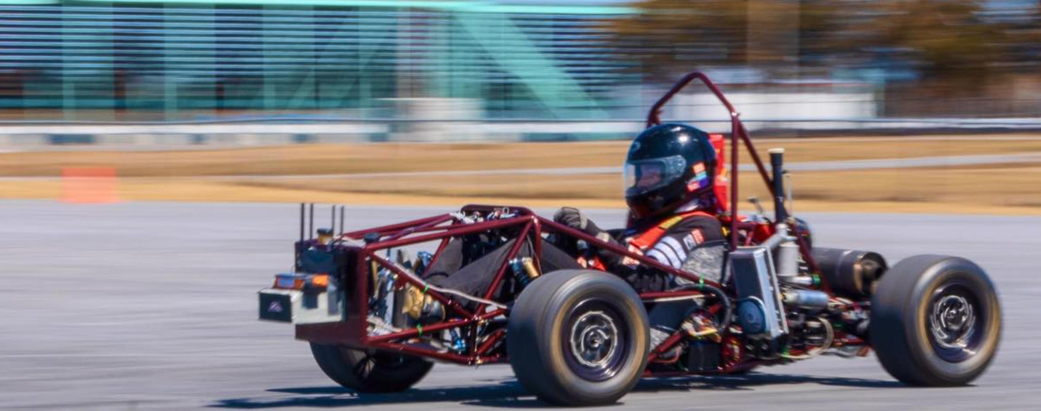
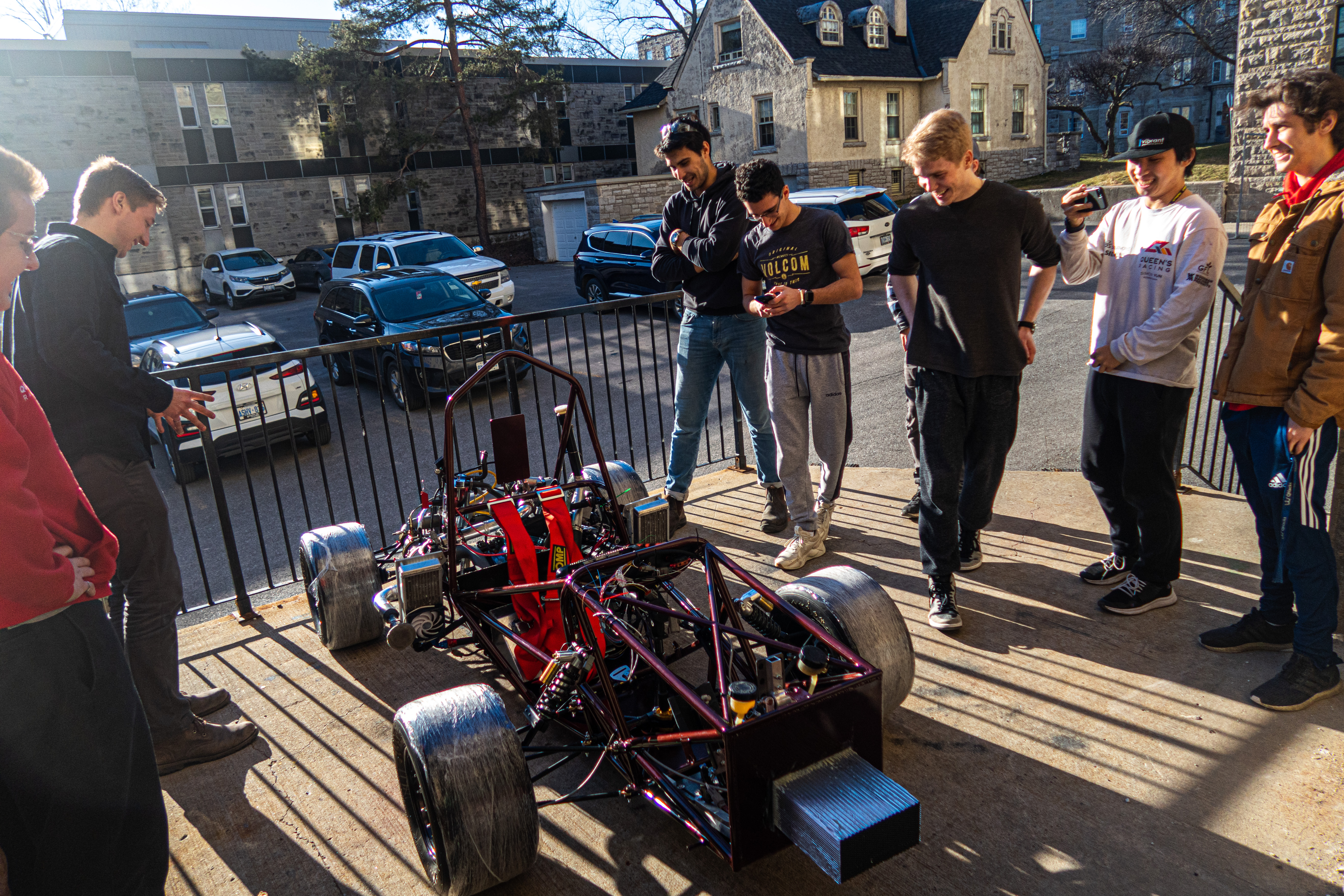
Photo/Video Gallery
Technical Implementation
Overview of the PDM15 CAN Interface
The PDM15 transmits and receives CAN messages carrying 8 bytes of data, where specific bytes and bits represent different outputs, voltages, currents, and fault statuses. The software implementation was tailored to the PDM15’s specific CAN message structure and multiplicative constants as detailed in its documentation.
CAN Data Mappings
Examples of key data mappings include:
- Throttle Potentiometer Voltage:
- CAN ID:
0x7F0 - Byte:
0 - Bitmask:
0xFF - Multiplier:
0.2 - Data Type:
Float
- CAN ID:
- Fuel Pump Current:
- CAN ID:
0x7F0 - Byte:
2 - Bitmask:
0xFF - Multiplier:
0.5 - Data Type:
Float
- CAN ID:
Each of these mappings was implemented in the software as a constexpr data structure in C++, encapsulating all relevant metadata for decoding or encoding the value.
Example data Structure
constexpr data ThrottlePotentiometerVoltage = {
    MOTEC_ID::PDM_1,   // CAN ID
    0,                 // Start Byte
    0xFF,              // Bitmask
    0.2,               // Multiplier
    DataType::Float    // Data Type
};
This structure allowed the software to generalize CAN message decoding, enabling a single function to extract the desired value for any data type based on its configuration.
Library Architecture
The library, implemented under the namespace CAL::DATA_PDM used an object-oriented approach to represent and manage the PDM’s inputs, outputs, and internal states. The key features of the library included:
1. CAN Message Parsing (Outbound Signal from PDM)
Functions parsed incoming CAN messages and extract the required data fields. For example, extracting the throttle potentiometer voltage involved:
- Identifying the CAN ID (
0x7F0). - Locating Byte 0 in the payload.
- Applying the bitmask (
0xFF). - Scaling the raw data using the multiplier (
0.2) from the documentation.
float parseThrottleVoltage(const CAN_msg_t &msg) {
    return (msg.data[ThrottlePotentiometerVoltage.start_idx] & ThrottlePotentiometerVoltage.bitmask)
           * ThrottlePotentiometerVoltage.multiplier;
}
These functions continuously decoded critical information for the driver on the dashboard and the pit crew used for debugging and real-time data monitoring.
2. CAN Message Construction (Inbound Signal to PDM)
Constructing outgoing CAN messages required encoding data into the appropriate bytes and applying scaling factors. For example, updating the fuel pump’s output voltage involved:
- Writing the scaled value to Byte 3.
- Ensuring alignment with the PDM’s CAN message structure.
void setFuelPumpVoltage(CAN_msg_t &msg, float voltage) {
    msg.data[FuelPumpVoltage.start_idx] = static_cast<uint8_t>(voltage / FuelPumpVoltage.multiplier);
}
This abstraction allowed other developers to control outputs without delving into the complexities of CAN message formatting.
3. Fault Monitoring
The library continuously monitored fault flags (e.g., over-current or under-voltage) accross the sensor suite by decoding status bytes from the PDM. For instance, a fault in the throttle body’s current output (Byte 6) was flagged as:
bool checkThrottleBodyFault(const CAN_msg_t &msg) {
    return (msg.data[tBStatusFault.start_idx] & tBStatusFault.bitmask) > 0;
}
4. Real-Time Diagnostics: Seeed Studio CAN Shield-Based Diagnostics Tool
To further support real-time diagnostics, I developed a standalone diagnostics tool using a Seeed Studio CAN shield. This tool enabled the team to monitor and debug CAN communication during development and testing.
The objective of this sub-project was to create a portable and efficient solution for capturing and printing CAN messages in real-time, providing engineers with visibility into the PDM15’s operation without requiring additional specialized hardware.
4. Real-Time Diagnostics: CAL-Integrated CAN Monitoring Tool
To enhance real-time diagnostics during racecar development, I engineered a standalone PDM CAN monitoring tool leveraging a Seeed Studio CAN Shield and the CAL (CAN Abstraction Layer) library. This tool enabled structured decoding of PDM messages and delivered immediate insight into system behavior without requiring a laptop or advanced data logger.
The goal of this tool was to provide engineers with a portable, interpretable, and real-time view of CAN traffic to and from the PDM, decoding meaningful fields such as voltages and currents using MoTeC calibration constants and formats.
Hardware Setup
- Arduino Uno + Seeed Studio CAN Shield (MCP2515, 8 MHz)
- Connected to a shared CAN bus running at 500 kbps
- Powered via USB for portability during vehicle testing
#include <mcp_can.h>
#include <SPI.h>
#include "cal.hpp"

MCP_CAN CAN(10);  // CS pin
CAL::CAL cal;     // CAL object

void printFloatVar(const char* label, const CAL::data& dataField) {
    float value;
    if (cal.returnVar(dataField, value) == 0) {
        Serial.print(label);
        Serial.print(": ");
        Serial.println(value, 3);
    }
}

void setup() {
    Serial.begin(115200);
    while (CAN.begin(MCP_ANY, 500000, MCP_8MHZ) != CAN_OK) {
        Serial.println("CAN init failed, retrying...");
        delay(1000);
    }
    Serial.println("CAN initialized successfully");
}

void loop() {
    unsigned char len = 0;
    unsigned char buf[8];

    if (CAN.checkReceive() == CAN_MSGAVAIL) {
        CAN.readMsgBuf(&len, buf);
        unsigned long canId = CAN.getCanId();

        // Build CAL-compatible message
        CAL::CAN_msg_t msg;
        msg.id = canId;
        msg.len = len;
        for (int i = 0; i < len; i++) {
            msg.data[i] = buf[i];
        }

        // Decode and update CAL internal state
        if (cal.updatePackage(msg) == 0) {
            Serial.print("Received 0x");
            Serial.println(canId, HEX);

            if (canId == CAL::MOTEC_ID::PDM_1) {
                printFloatVar("ThrottlePot V", CAL::DATA_PDM::ThrottlePotentiometerVoltage);
                printFloatVar("Battery V", CAL::DATA_PDM::BatteryVoltage);
                printFloatVar("Fuel Pump I", CAL::DATA_PDM::FuelPumpCurrent);
                printFloatVar("Fuel Pump V", CAL::DATA_PDM::FuelPumpVoltage);
                printFloatVar("Kill Switch V", CAL::DATA_PDM::KillSwitchVoltage);
                printFloatVar("Throttle Body I", CAL::DATA_PDM::ThrottleBodyCurrent);
                printFloatVar("Throttle Body V", CAL::DATA_PDM::ThrottleBodyVoltage);
                Serial.println("---");
            }

            if (canId == CAL::MOTEC_ID::PDM_2) {
                printFloatVar("Fuel Injector I", CAL::DATA_PDM::FuelInjectorCurrent);
                printFloatVar("Fuel Injector V", CAL::DATA_PDM::FuelInjectorVoltage);
                Serial.println("---");
            }
        } else {
            Serial.print("Unhandled CAN ID: 0x");
            Serial.println(canId, HEX);
        }
    }
}
Benefits to Development Workflow
- Structured Decoding: Uses CAL to convert raw data into interpretable, engineering-accurate units.
- Real-Time Feedback: Helps engineers instantly validate PDM outputs during bench testing.
- Fault Insight: Flags under-voltage, over-current, or disconnected subsystems on the fly.
This CAL-integrated diagnostic tool became a vital part of our real-time validation framework, reducing diagnosis time and enabling the team to rapidly iterate and debug the PDM15 integration into the vehicle during the pre-season.
Challenges and Solutions
Handling CAN Message Timeouts
To ensure the system remained stable when CAN messages were delayed or lost, default timeout behaviors were implemented. For example, if the throttle voltage message timed out, its value was reset to 0.0.
float throttleVoltage = (timeout) ? 0.0f : parseThrottleVoltage(msg);
Debugging Complex Faults
Some faults were intermittent and brief, requiring extensive logging and review of CAN messages. I wrote a logging utility to continuously monitor the messages and have any odd results (outside of expected ranges) persist untilk review, which aided in the identification of issues.
Collaboration with the Electrical Team in Q23
While my focus was on the software, I collaborated with the electrical engineers during system integration. This included:
- Assembly of Wiring Loom: Ensured the wiring adhered to MoTeC’s CAN bus specifications, including proper use of terminating resistors. Followed the competition rules closely during the assembly process.
- Testing Outputs: Assisted in debugging output channels by sending test CAN messages from my software to toggle outputs (e.g., fuel pumps, fans).
- Fault Simulation: Simulated fault conditions (e.g., short circuits) to validate the PDM’s fault-handling logic.
- Collaboration with Electrical Systems Lead: Communicated with my mentor, Ethan, to gain crucial insights into the overall design of the car’s electrical system and ensure compliance with competition guidelines.
I also communicated with the dashboard team to assess their requirements.
The library was integrated, finalized, deployed, and further tested by Jacob Chisholm’s CAN Bus Abstraction Layer (CAL) library.
Results and Impact
The developed software helped the team by integrating the PDM into the ECU and dashboard. This enabled power management and diagnostics for our racecar:
- Reliability: The PDM15 handled all power distribution seamlessly, with software-controlled fault recovery.
- Real-Time Insights: Drivers and engineers could monitor critical metrics fromt he PDM (e.g., battery voltage, output currents) in real-time via the dashboard.
- Reduced Debugging Time: The diagnostic capabilities of the library helped identify and resolve wiring or configuration issues quickly.
The reusable C++ library became a cornerstone of our vehicle’s electrical system, enabling future team members to build upon a reliable and extensible foundation.
Conclusion
This project highlighted the importance of working collaboratively on robust software to enable advanced hardware like the PDM15 to perform in a high-stakes motorsport environment. By working on the development of a flexible and feature-rich library, I contributed to the overall success of our Formula SAE vehicle for years to come.