Q25 EV CAN Architecture Overhaul
Introduction
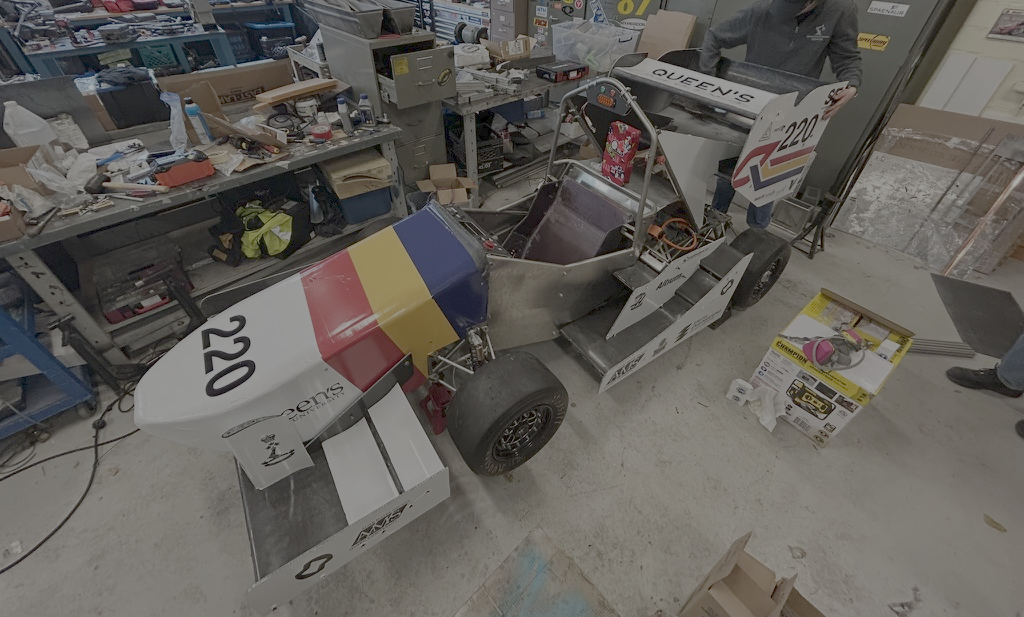
With the transition from our combustion-powered Q23 platform to the fully electric Q25 vehicle, I led the computer system integration effort for the year. Once we had our new EV components, I architected two flagship projects: a real-time telemetry system and a complete CAN architecture overhaul. This post details our CAN redesign, leveraging experiences and code from Q23 to support new EV hardware and laying the groundwork for comprehensive sensor integration.
Background: Lessons from Q23
In Q23, our CAN Abstraction Layer (CAL) library focused on interfacing a MoTeC PDM15. Key features included:
- Signal descriptors (
datastructs) for mapping PDM CAN IDs and scaling factors. - Parsing logic in
CAL::DATA_PDMto decode voltages, currents, and fault flags. - Diagnostics tool using a Seeed CAN Shield + CAL for real-time traffic decoding.
While the Q23 code provided a solid foundation, supporting the new EV components required a more flexible, device-agnostic approach.
Architecture Redesign for Q25
Decentralized CAN Network
Rather than a monolithic PDM-driven bus, Q25’s system is fully decentralized:
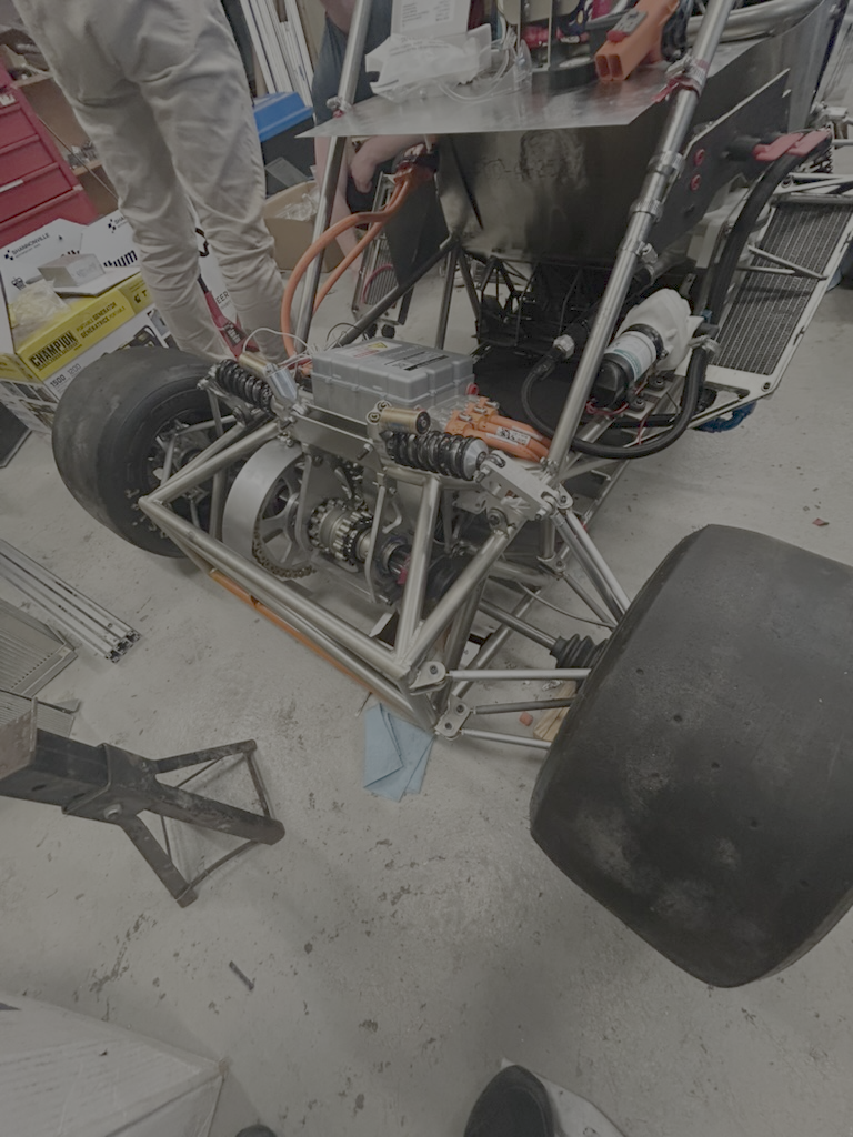
- Inverter (Cascadia CM200DX) broadcasts telemetry on its CAN channel.
- Battery Management System (Orion BMS2) publishes cell voltages, temperatures, and health metrics.
- Sensor nodes (temperature, pressure, current) each host an MCP2515 interface, relaying data independently.
A central dashboard STM32 board acts as the VCU. It is located in the dashboard behind the steering wheel, and subscribes to all topics. On its screen, it displays relevant info like the battery voltage and wheel speed sensor readings to the driver. Behind the scenes, it continuously logs information about the car’s state, and it connects via a WIFI signal to our track laptops, providing diagnostics during testing and setup. It also interfaces over CAN with a lightweight PDM (from our electrical lead Cianchetti’s capstone project) to issue control commands to actuators such as our fault relays.
Component CAN IDs & Mapping
We defined new commands.hpp entries for inverter control and status:
static const data TORQUE = { CAN_ID::INVERTER + 0xC0u, 0, 2, 0xFF, 10, DataType::int16 };
static const data SPEED  = { CAN_ID::INVERTER + 0xC0u, 2, 2, 0xFF, 1,  DataType::int16 };
For the Orion BMS2, we mirrored these patterns in a new bms.hpp, defining IDs and scaling factors according to its documentation.
Code Refactoring & Proof of Concept
Building on the Q23 CAL, we extended cal.hpp to register multiple devices:
int CAL::updatePackage(CAN_msg_t &msg) {
    switch (msg.id) {
        case CAN_ID::INVERTER: return inverter.handleMessage(msg);
        case CAN_ID::BMS:      return bms.handleMessage(msg);
        default:               return genericSensor.handleMessage(msg);
    }
}
Adapted from zenith/cal/src/cal.cpp
Key changes included:
- Dynamic dispatch to support new device handlers.
- Generic class that maps arbitrary CAN frames into sensor readings.
- Preserved Q23 parsing logic for PDM messages to maintain backwards compatibility.
Deep Dive: Code Walkthrough with Actual Project Files
Before we dive into functions, here’s the directory structure:
platformio.ini
include/
    commands.hpp
lib/
    CAL25/
        data_structs.hpp
        cal.hpp
        cal.cpp
        inverter.hpp
        inverter.cpp
src/
    main.cpp
    sender.cpp
    receiver.cpp
1. Processing Incoming CAN Messages
We dispatch every received frame via CAL::updatePackage in lib/CAL25/cal.cpp:
// lib/CAL25/cal.cpp (simplified)
int CAL::updatePackage(CAN_msg_t &msg) {
    switch (msg.id) {
        case CAN_ID::INVERTER:
            inverter_data = msg;             // store raw frame
            return inverter.handleMessage(msg);
        default:
            Serial.print("Unknown ID: ");
            Serial.println(msg.id);
            return 1;
    }
}
- cal.hpp declares
class CALwith anInverter inverter;member. - Incoming frames with
CAN_ID::INVERTERget copied intoinverter_data. inverter.handleMessage(in lib/CAL25/inverter.cpp) unpacks fields:- Masks to 11-bit ID, computes sub-index (
idx). - Uses a
switch(idx)to decode temperatures, currents, voltages, etc. - Helpers in data_structs.hpp (
toSigned,extractBits) convert raw bytes.
- Masks to 11-bit ID, computes sub-index (
2. Generating & Sending Outgoing CAN Messages
When we need to send a command (e.g., torque), we call CAL::updateVar:
// lib/CAL25/cal.cpp (packing helper usage)
void CAL::updateVar(const data &d, int value) {
    CAN_msg_t &pkg = package(d.id); // returns inverter_data or fallback
    pkg.id  = d.id;
    pkg.len = d.len;
    varToBuf(pkg, d, value);       // pack into pkg.data[]
}
- include/commands.hpp defines
datadescriptors for TORQUE, SPEED, etc. varToBufwrites the integer/float/boolean into the proper bytes usingd.dataType.- In src/main.cpp, after
updateVaryou call:sendCan(cal.package(CAL::CMD::TORQUE));where
sendCanwrapsCAN_msg_tinto acan_frameand invokesmcp2515.sendMessage().
3. Putting It All Together in main.cpp
// src/main.cpp (receive & send flow)
if (mcp2515.readMessage(&rx) == ERROR_OK) {
    CAN_msg_t m{rx.can_id, {0}, uint8_t(rx.can_dlc), 0,0,0};
    memcpy(m.data, rx.data, rx.can_dlc);
    cal.updatePackage(m);    // parse incoming into inverter state
}

// … user selects “Send torque” …
cal.updateVar(CAL::CMD::TORQUE, torqueVal);           // pack data
sendCan(cal.package(CAL::CMD::TORQUE));               // transmit frame
This object-oriented design cleanly separates:
- Frame routing & storage (
CAL/ cal.cpp), - Field packing/unpacking (
varToBuf/bufToVarin cal.cpp), - Domain parsing & state (
Inverter::handleMessagein inverter.cpp), - User interaction & actual CAN I/O (
main.cpp,sender.cpp,receiver.cpp).
Click here for the full code branch.
Integration
Challenges
Oscilloscope-Assisted BMS Debugging: To diagnose why the Orion BMS2 wouldn’t speak with its Utility software, we wired CAN1 through a custom Arduino interface and captured traffic on a Tektronix scope. Signals showed correct bit timing, outputting an error code, and failed to initialize—leading us to confirm that the Orion firmware strictly requires its proprietary CANdapter for bus arbitration, and our open-source interface code loaded onto a previous Seeed Studio CAN Shield Arduino was incompatible.
Molex 48-Pin Programming Harness:
Per the Cascadia PM/RM/CM hardware manual, we fabricated a test-bench harness around the inverter’s Molex 48-pin connector to flash the bootloader and program it for the first time. This challenge highlighted the delicacy of the connector, as improper pin seating often caused intermittent errors. At times, the inverter would become completely unresponsive, requiring a full power cycle to recover.
To mitigate these issues, we implemented a meticulous quality control review of this connector, verifying continuity with a multimeter before our programming session. This extra care ensured reliable connections and minimized downtime during firmware updates and diagnostics.
Pin 12: chassis ground
Pin 15: /PROG_ENA
Pins 23/24: CAN_H/CAN_L
Pin 37: 5 V logic supply (bootloader)
Firmware Flashing Procedures
Reliable firmware alignment was critical before dynamic testing:
CM200 Inverter and Orion BMS2 Flash: Collaboration with Other Teams:
Prior to the New Hampshire design competition, we encountered several challenges with getting our CM200 inverter and Orion BMS2 to be flashed with the correct hardware that would allow it to run within normal parameters according to the manual. To overcome these hurdles, we reached out to other teams for insights into their approaches. This collaboration proved invaluable, as many teams had faced similar issues.
One team shared their experience with the CM200 inverter, highlighting the importance of precise timing during the bootloader flashing process. They also shared tips on configuring the Orion Utility software to avoid common pitfalls.
These discussions not only helped us troubleshoot our immediate issues but also fostered a sense of camaraderie and knowledge-sharing within the competition. By incorporating these lessons, we would be able to tune our Hardware components, which was a new feat for the team.
From these discussions, we performed a smooth firmware update to the latest Orion Utility build. The process completed without errors, and post-flash self-tests passed.
Next Steps
- Validate end-to-end CAN path and node health via a real-time logging utility. This will serve as a bare program for a Telemetry System.
- Roll out MCP2515-based modules for brake pressure, accelerator travel, and ambient conditions.
- Wire up the dashboard’s MCP-based display code to display inverter RPM, BMS voltages, and live sensor metrics.
Conclusion
The refactoring of the CAN architecture for the car allows us to start the integration process for the rest of the system. This library allows the expansion room for subsequent years team members to add and swap out EV components as the complexity of the car increases.