Payload Delivery Mechanism for a Drone
Overview
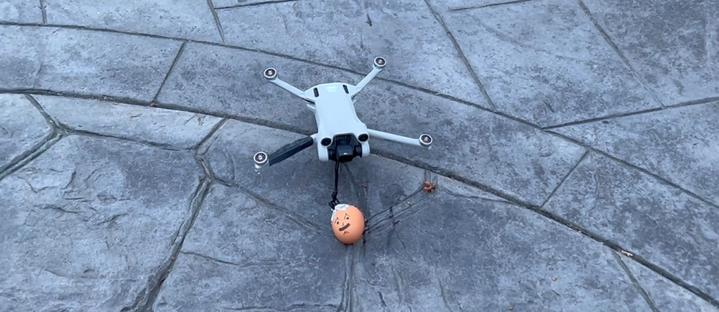
This embedded system project showcases a payload delivery mechanism designed for a DJI Mini 3 Pro, utilizing a HELTEC ESP32 microcontroller, a photoresistor, and a custom 3D printed housing. By detecting light from the drone’s recording indicator, the mechanism actuates a servo motor attached to the bottom of the drone, releasing a payload attached to a string. This mechanism was demonstrated through an “egg drop” test, combining principles of microcontroller programming, circuit design, and mechanical engineering.
Objectives
- Develop a lightweight payload release system that can be triggered remotely. To do this, I had to be able to control a servo motor to open a hook and release the payload and encapsulate this in a lightweight housing using 3D printing.
Key Components
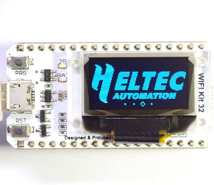
- Microcontroller: HELTEC ESP32.
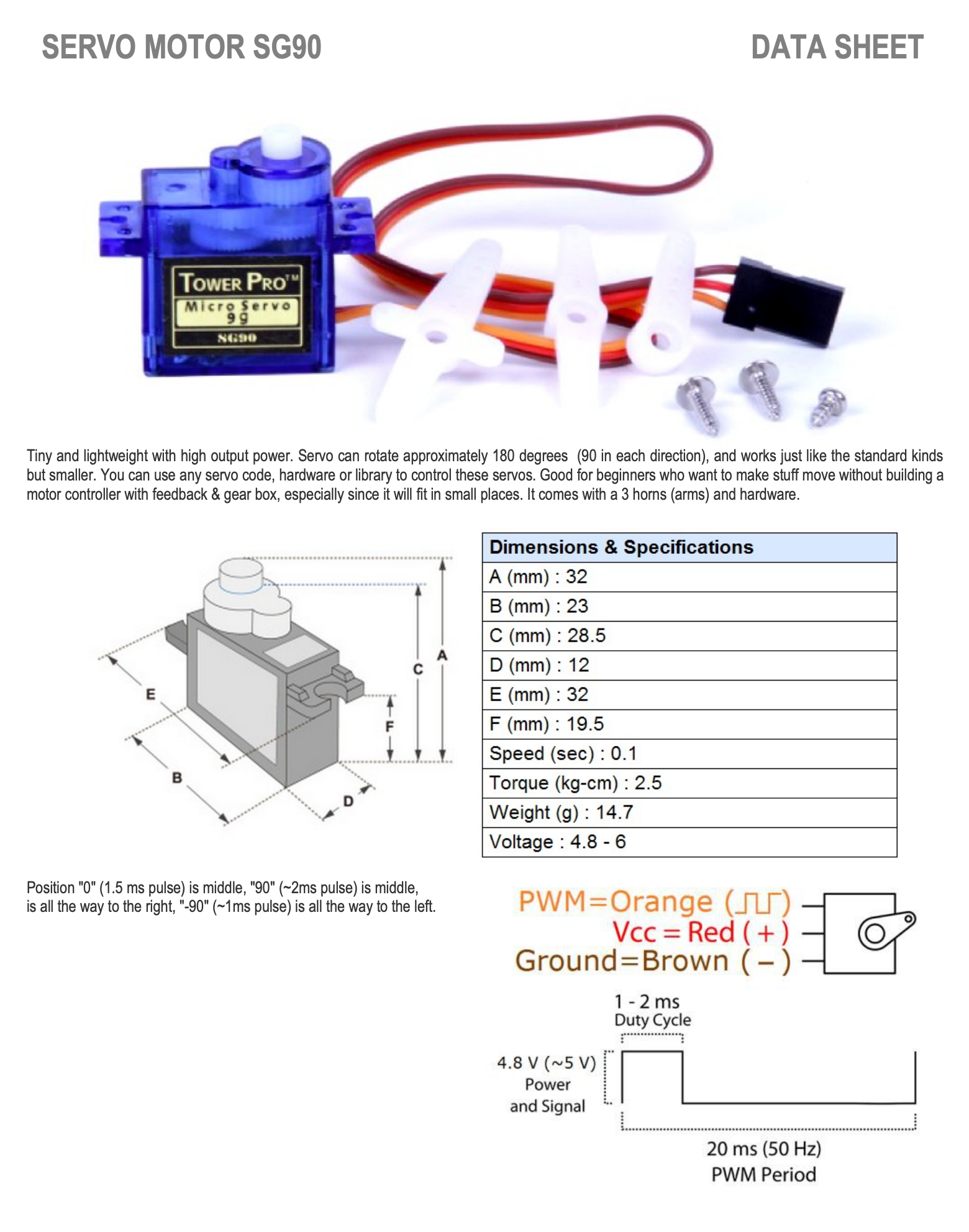
- Actuator: Servo motor controlled via PWM signals.
- Sensor: Photoresistor to detect light and trigger the release.
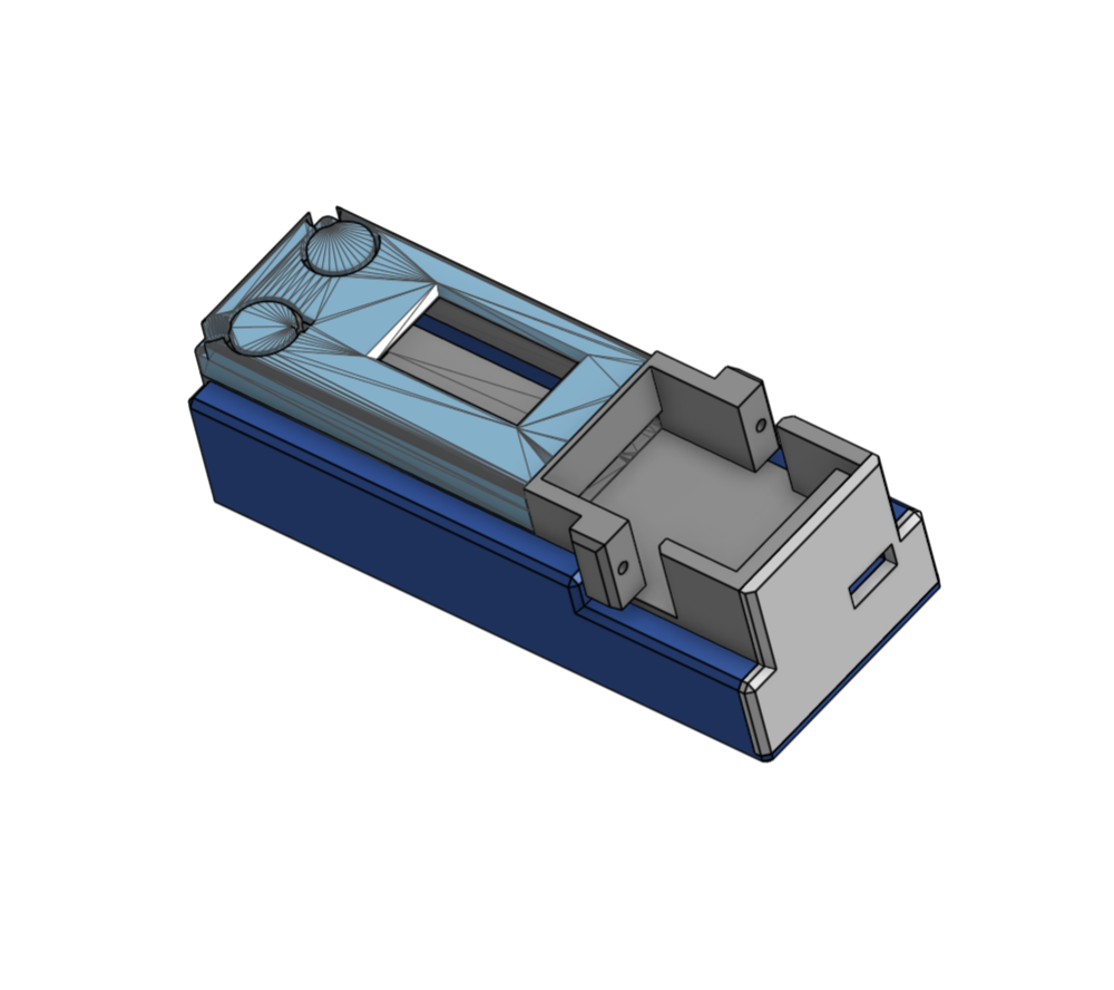
- Housing: Custom 3D-printed enclosure designed to attach to the bottom of the drone, and house the microcontroller, battery, servo, and sensors.
- Software: Custom drivers for servo control and light detection algorithm tuning.
Implementation Details
Hardware Design
The payload mechanism relies on reliable control of the servo motor to ensure that the payload drops at the right time. A photoresistor connected to the ESP32 detects the drone camera’s light signal, triggered by a button on the remote, causing the servo’s hook to rotate, and the payload to drop. The system was housed in a custom-designed, 3D-printed enclosure to fit on the bottom of the drone, and consideration for size and weight was made since this is only a micro-drone.
- 3D Printing: The housing was designed using Onshape CAD software and manufactured with an FDM printer using PLA. Separate enclosures were created for the ESP32 and servo motor. They were then fused together with superglue, and the servo was fastened with bolts through tabs on the PLA. Ths allowed all of the wiring and battery to stay hidden. The hosuing had to be shaped to fit in a specific location under the drone to avoid interfering with the low altituide sensor.
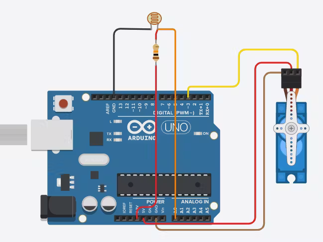
- Circuit Assembly: The photoresistor was soldered to a 10kohm resistor, providing an analog input to the ESP32. The servo motor was wired directly to the microcontroller’s PWM output.
Software Development
The software consists of an object-oriented control program written in C++ for the ESP32, with custom servo drivers for the SG90 to optimize timing and motion accuracy so the hook would release successfully.
- Servo Control: The servo was driven using PWM signals generated by the ESP32. The implementation allowed for precise control of the angle and release timing.
- Light Detection: The photoresistor’s output was continuously monitored. When the light intensity crossed a predefined threshold I determined through bench testing, the servo was actuated.
#ifndef ESP32_Servo_h
#define ESP32_Servo_h

#define ESP32_Servo_VERSION 1 // Library version

// Default pulse width values for servos
#define DEFAULT_uS_LOW 400
#define DEFAULT_uS_HIGH 2500

// PWM timer settings
#define DEFAULT_TIMER_WIDTH 10
#define DEFAULT_TIMER_WIDTH_TICKS 1024
#define MINIMUM_TIMER_WIDTH 10
#define MAXIMUM_TIMER_WIDTH 20

// Pulse width constraints
#define MIN_PULSE_WIDTH 500 // Minimum pulse sent to a servo in microseconds
#define MAX_PULSE_WIDTH 2500 // Maximum pulse sent to a servo in microseconds
#define DEFAULT_PULSE_WIDTH 1500 // Default pulse width when servo is attached
#define DEFAULT_PULSE_WIDTH_TICKS 4825
#define REFRESH_CPS 50 // Refresh rate in Hz
#define REFRESH_USEC 20000 // Refresh period in microseconds

#define MAX_SERVOS 16 // Maximum number of PWM channels on ESP32

class Servo {
public:
    Servo();
    int attach(int pin); // Attaches a servo to a pin
    int attach(int pin, int min, int max); // Attaches a servo with custom pulse width range
    void detach(); // Detaches the servo
    void write(int value); // Sets the servo angle or pulse width in microseconds
    void writeMicroseconds(int value); // Sets the servo pulse width in microseconds
    int read(); // Returns the last set servo angle
    int readMicroseconds(); // Returns the last set servo pulse width in microseconds
    bool attached(); // Checks if the servo is attached

    // ESP32 specific functions
    void setTimerWidth(int value); // Sets the PWM timer width
    int readTimerWidth(); // Returns the current PWM timer width

private:
    int usToTicks(int usec); // Converts microseconds to ticks
    int ticksToUs(int ticks); // Converts ticks to microseconds
    void setupPwmChannel(); // Sets up the PWM channel

    static int ServoCount; // Total number of attached servos
    static int ChannelUsed[MAX_SERVOS]; // Tracks whether a channel is in service

    int servoChannel; // Channel number for this servo
    int min; // Minimum pulse width for this servo
    int max; // Maximum pulse width for this servo
    int pinNumber; // GPIO pin assigned to this channel
    int timer_width; // PWM timer width
    int ticks; // Current pulse width in ticks
    int timer_width_ticks; // Number of ticks at rollover
};

#endif // ESP32_Servo_h
#include "Arduino.h"
#include "ESP32Servo.h"

Servo myservo; // Create servo object

int servoPin = 1; // Servo connected to GPIO pin 35
int photoresistorPin = 2; // Photoresistor connected to GPIO pin 34

int lightThreshold = 500; // Threshold for light level to open the servo


void setup() {
    Serial.begin(115200);
    myservo.attach(servoPin);
    pinMode(photoresistorPin, INPUT);

    // Move servo to closed position on boot
    Serial.println("Moving to closed state.");
    myservo.write(0);
    delay(60000); // Wait a minute to start the recording
}

void loop() {
    int lightLevel = analogRead(photoresistorPin);
    Serial.print("Light level: ");
    Serial.println(lightLevel);

    if (lightLevel > lightThreshold) {
        Serial.println("Light threshold exceeded. Moving to open state.");
        myservo.write(90); // Move servo to open state
    }

    delay(100); // Short delay for loop stability and to avoid flooding the serial output
}
Testing and Results
Egg Drop Test
To validate the mechanism’s reliability, a series of tests were conducted using an egg as the payload. The drone successfully delivered the payload with precision, and had no accidental releases. The drone had some trouble with a swaying payload as a function of the length of the string. The string however could not be shortened too much as to interfere with the drone’s altituide sensor.
Observations
The 3D-printed housing effectively protected the electronics and maintained structural integrity. The servo driver performed well under varying conditions, with minimal latency in response to the button press. I was able to drop the egg deterministically.
Challenges and Lessons
- Servo Tuning: Fine-tuning the servo’s pulse width was crucial for achieving consistent release behavior for the swing.
- Soldering: This was my first time soldering components to the microcontroller directly, which required careful attention.
Future Improvements
- Reduce Weight: Maybe designing two separate modules for the microcontroller and servo would reduce the package size on the bottom of the drone, and better distribute the weight of the system.
- Special Design: Building a drone specifically for this purpose would allow for higher carrying load capacity and a better integrated package.
Resources
This project paves the way for further exploration into drone automation and robotics.